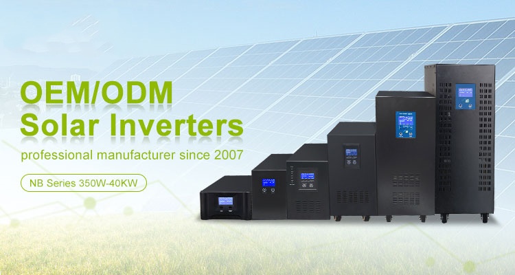
■ Micro Inverter Solar Panel System Feature
1 Solar micro inverter built-in MPPT or PWM charge controller optional.
2 Pure sine wave output.
3 Wide AC voltage input range, AVR output.
4 Adopt traditional EI transformer , stable performance.
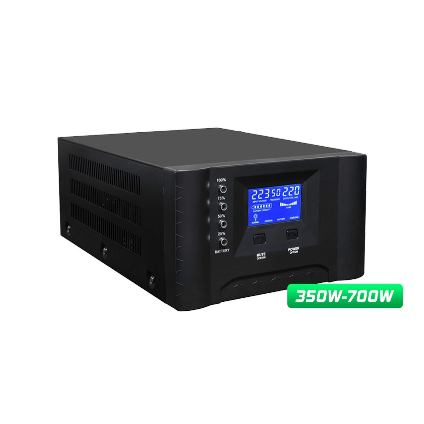
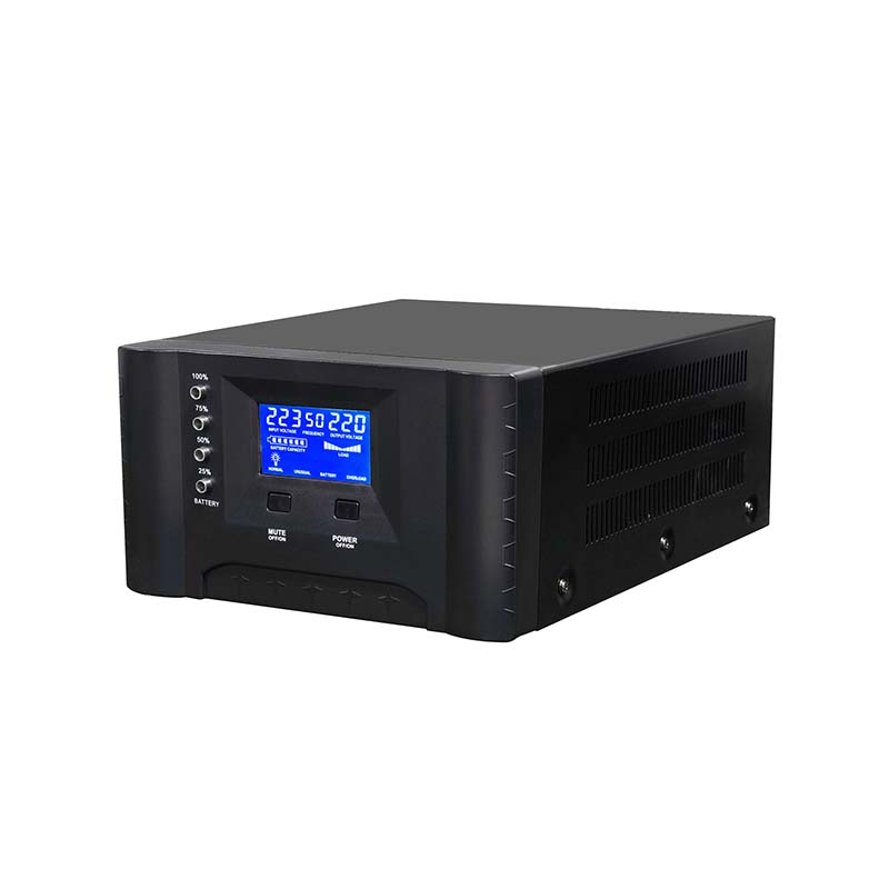
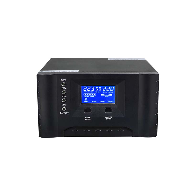
5 LCD/LED&LCD real-time display, concise and straightforward.
6 Working modes: AC first or battery first optional, intelligent charging.
7 RS232 communication port optional.
■ Micro Inverter Solar Panel System Specification
| Specification | |||||
| Model NB-T | 35112/24 | 50112/24/48 | 60112/24/48 | 70124/48 | |
| Rated Power | 350W | 500W | 600W | 700W | |
| Peak Power(20ms) | 1050VA | 1500VA | 1800VA | 2100W | |
| Start Motor | 0.3HP | 0.5HP | 0.5HP | 0.5HP | |
| Battery Voltage | 12/24VDC | 12/24/48VDC | 24/48VDC | ||
| Size(L*W*Hmm) | 335*210*122 | ||||
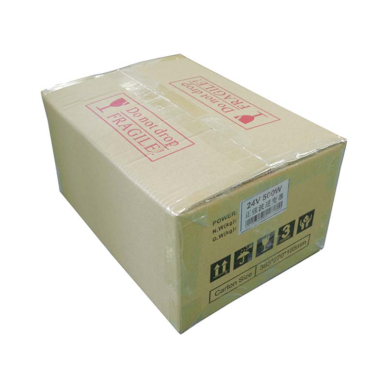
| Packing Size(L*W*Hmm) | 385*270*185(1pc) / 400*280*400(2pcs) | ||||
| N.W.(kg) | 6.5 | 8 | 9 | 10 | |
| G.W.(kg)(Carton Packing) | 7.5 | 9 | 10 | 11 | |
| Installation Method | Desktop | ||||
| Parameter | |||||
| Input | DC Input Voltage Range | 10.5-15VDC(Single battery voltage) | |||
| AC Input Voltage Range |
73VAC~138VAC(110VAC) / 83VAC~148VAC(120VAC) / 145VAC~275VAC(220VAC) /
155VAC~285VAC(230VAC) / 165VAC~295VAC( 240VAC)
|
||||
| AC Input Frequency Range | 45Hz~55Hz(50Hz) / 55Hz~65Hz(60Hz) | ||||
| Max AC charging current | 6A~15A(Depending on the model) | ||||
| AC charging voltage | LEAD battery:Charge Voltage :14.2V; Float Voltage:13.8V(Single battery voltage) | ||||
| AC charging method | Three-stage (constant current, constant voltage, floating charge) | ||||
| Output | Efficiency(Battery Mode) | ≥85% | |||
| Output Voltage(Battery Mode) | 110VAC±2% / 120VAC±2% / 220VAC±2% / 230VAC±2% / 240VAC±2% | ||||
| Output Frequency(Battery Mode) | 50Hz±0.5 or 60Hz±0.5 | ||||
| Output Wave(Battery Mode) | Pure Sine Wave | ||||
| Efficiency(AC Mode) | >99% | ||||
| Output Voltage(AC Mode) | Follow input | ||||
| Output Frequency(AC Mode) | Tracking Automatically | ||||
|
Output waveform distortion
(Battery Mode)
|
≤3%(Linear load) | ||||
| No load loss(Battery Mode) | ≤2.5% rated power | ||||
| No load loss(AC Mode) | ≤2% rated power( charger does not work in AC mode) | ||||
| No load loss(Energy saving Mode) | ≤10W | ||||
| Battery Type | VRLA Battery | Charge Voltage :14.2V; Float Voltage:13.8V(Single battery voltage) | |||
| Customize battery | Charge and discharge parameters of different types of batteries (such as lithium batteries, etc.) can be customized according to user requirements | ||||
| Protection | Battery undervoltage alarm | Factory default: 11V(Single battery voltage) | |||
| Battery undervoltage protection | Factory default: 10.5V(Single battery voltage) | ||||
| Battery overvoltage alarm | Factory default: 15V(Single battery voltage) | ||||
| Battery overvoltage protection | Factory default: :17V(Single battery voltage) | ||||
| Battery overvoltage recovery voltage | Factory default: 14.5V(Single battery voltage) | ||||
| Overload power protection | Automatic protection (battery mode), circuit breaker or insurance (AC mode) | ||||
| Inverter output short circuit protection | Automatic protection (battery mode), circuit breaker or insurance (AC mode) | ||||
| Temperature protection | >90°C(Shut down output) | ||||
| Alarm | A | Normal working condition, buzzer has no alarm sound | |||
| B | Buzzer sounds 4 times per second when battery failure, voltage abnormality, overload protection | ||||
| C | When the machine is turned on for the first time, the buzzer will prompt 5 when the machine is normal | ||||
|
Inside Solar controller
(Optional)
|
Charging Mode | PWM | |||
| Charging current | 10A~30A | ||||
| PV Input Voltage Range | 15V-44V(12V System); 30V-44V(24V System); 60V-88V(48V System) | ||||
|
Max PV Input Voltage(Voc)
(At the lowest temperature)
|
50V(12V/24V System); 100V(48V System) | ||||
| PV Array Maximum Power |
12V System: 140W(10A)/280W(20A)/420W(30A);
24V System: 280W(10A)/560W(20A)/840W(30A);
48V System: 560W(10A)/1120W(20A)/1680W(30A)
|
||||
| Standby loss | ≤3W | ||||
| Maximum conversion efficiency | >95% | ||||
| Working Mode | Battery First/AC First/Saving Energy Mode | ||||
| Transfer Time | ≤4ms | ||||
| Display | LCD | ||||
| Thermal method | Cooling fan in intelligent control | ||||
| Communication | RS232(Optional) | ||||
| Environment | Operating temperature | -10℃~40℃ | |||
| Storage temperature | -15℃~60℃ | ||||
| Noise | ≤55dB | ||||
| Elevation | 2000m(More than derating) | ||||
| Humidity | 0%~95% ,No condensation | ||||
| Note: All specifications are subject to charge without prior notice | |||||
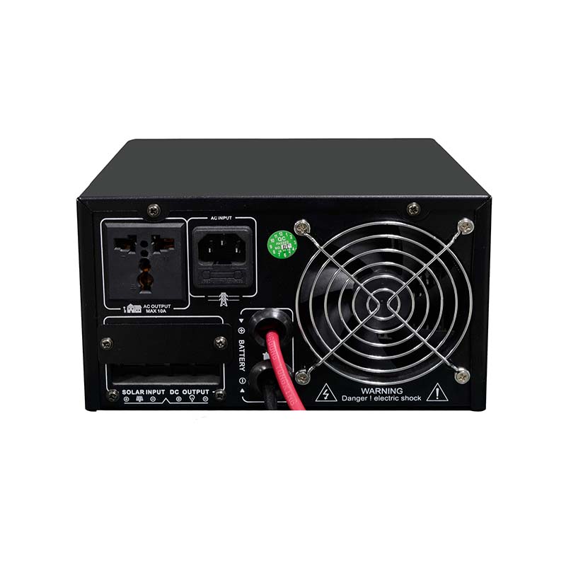
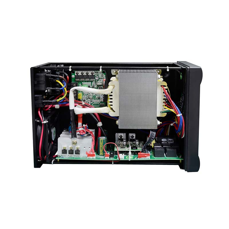
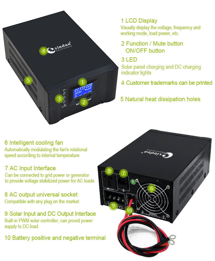
■ Micro Inverter Solar Panel System Details
■ Micro Inverter Solar Panel System Wiring Diagram 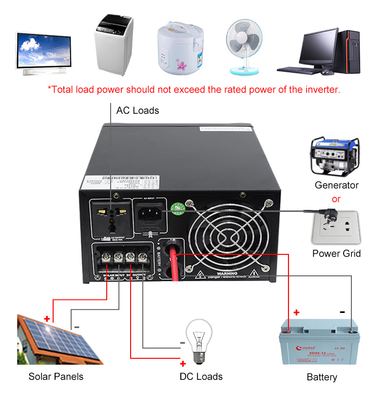
BigBear LLC micro inverter solar system usually has two application methods:
1. Home backup system:
When AC grid power is available, inverter charges battery, at the same time, AC grid power bypass and stable voltage through inverter to home appliances, such as light, fan, rice cooker, kettle. When AC grid power is off, inverter will automatic transfer switch to battery power and convert DC to AC power.
2. Wind or Solar Energy system:
The electricity generated by solar or wind energy is DC (direct current), then inverter will convert DC to AC power. When battery power is lacking, it will automatic transfer to grid power for powering continuously.
■ Micro Inverter Solar Panel System Application

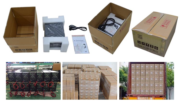
■ Inverter Package and Delivery 